

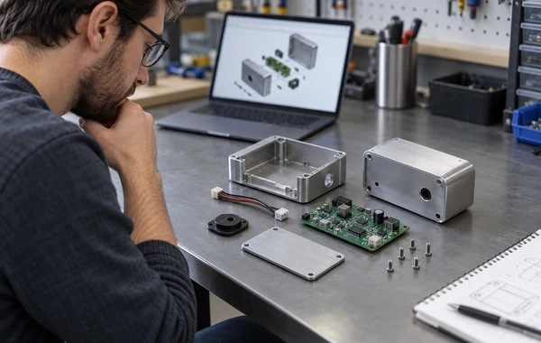
How to Coordinate Mechanical Parts, PCBA and Final Assembly for a New Product Build
To coordinate mechanical parts, a printed circuit board assembly (PCBA) and final assembly, release them as one product configuration. Use a product-level bill of materials (BOM), controlled interface dimensions, matching revision identifiers, an agreed assembly sequence and a test plan with measurable pass criteria. Each subassembly can have its own drawing package, but the top-level release must say which versions belong together.
Parts can pass inspection separately and still fail during integration. A connector may sit a few millimetres behind its enclosure opening. A cable that worked in the prototype may become impossible to install after a bracket changes. Firmware may expect a sensor revision that purchasing has replaced. These are product-level problems, and separate supplier inspections will not catch all of them.
Multi-process build controls at a glance
| Control item | What it should answer | Release evidence |
|---|---|---|
| Product configuration | Which mechanical, electronic, cable and firmware revisions form one build? | Top-level BOM and release note |
| Interface definition | Where and how do subassemblies meet? | Controlled datums, connector locations, stack heights and mating-part references |
| Responsibility map | Who approves design, sourcing, substitutions, firmware and test results? | Named owner for each decision and approval route |
| Assembly sequence | In what order can parts be installed, connected and serviced? | Assembly drawing, work instruction or pilot-build record |
| Acceptance plan | What must pass before the unit ships? | Inspection and test plan with limits and required records |
| Change control | How are deviations and new revisions introduced? | Change notice, affected-item list and disposition of existing stock |
Treat this table as a planning aid. The controls still need to reflect the product, regulatory obligations, quantities, supplier structure and consequences of failure.
1. Define the product configuration before requesting a quote
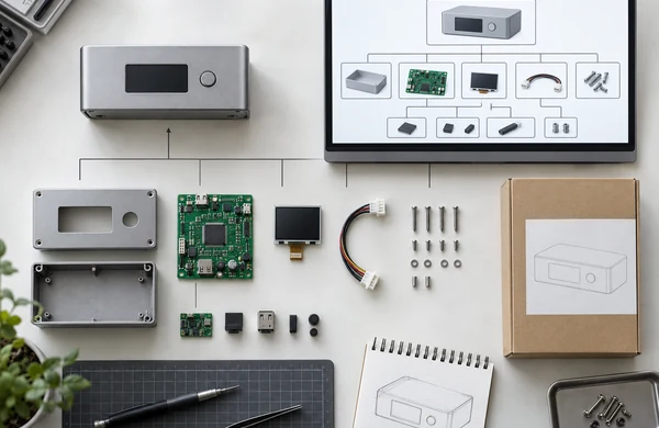
Start with the sellable or testable unit, not with a folder of unrelated component files. Give the product a part number and revision. Beneath it, list every controlled subassembly: enclosure, machined parts, moulded parts, PCBA, display, cable set, fasteners, labels, firmware and packaging where packaging affects shipment or traceability.
A product BOM works best as a hierarchy. The top level identifies the finished unit. Below it sit the buildable subassemblies, each linked to its own controlled details. The mechanical and electronics BOMs then remain parts of the same release instead of becoming separate versions of the product.
At the product level, record:
- Item number and revision for every subassembly
- Quantity per finished unit
- Make, buy or customer-supplied status
- Approved manufacturer part number where purchasing choice matters
- Firmware or programmed-device version
- Do-not-fit and variant rules
- Reference to the drawing, specification or test instruction
- Substitution and approval authority
Do not place several possible revisions on the same released BOM line and expect production to choose. If variants share a base design, give each variant a clear configuration or option rule.
The manufacturing RFQ checklist covers the general files and commercial information needed for a quote. A multi-process product needs one extra layer: an explicit map showing how the separate packages combine into the requested unit.
2. Freeze interfaces before refining individual parts
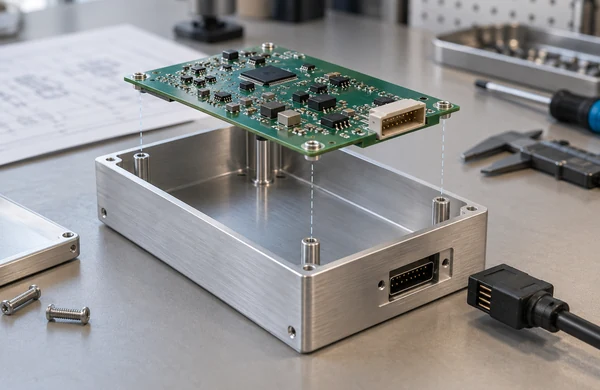
Integration trouble often appears at an interface. The enclosure, PCBA and cable set may each meet its own drawing while their shared geometry remains undefined.
Review the assembled CAD model and identify the features that control fit or function:
- PCBA mounting datums, standoff positions and screw access
- Connector location relative to the finished enclosure opening
- Display window position, viewing angle and retention method
- Stack height between board, thermal pad, heatsink and cover
- Cable exit, bend space, strain relief and connector latch access
- Grounding contacts, conductive finishes and masked areas
- Gasket compression and sealing surfaces when applicable
- Moving-part clearance and service-removal path
Dimension these relationships from stable datums on the finished parts. Avoid controlling the same interface from two unrelated drawing origins. If geometric dimensioning and tolerancing is used, state the governing drawing standard and revision. ASME Y14.5 defines rules and symbols for communicating geometric requirements, but the designer still has to choose datums and tolerances that match the product’s function.
Nominal CAD alignment is not an acceptance rule. The drawing should say how far the connector, board or mating feature may move before assembly or function is affected. Tight control belongs on the interfaces that need it, not on every dimension.
3. Connect the mechanical BOM, PCBA BOM and firmware release
The product BOM should link three kinds of information that often live in different systems.
The mechanical package identifies manufactured parts, purchased hardware, finishes and assembly drawings. The PCBA package contains fabrication data, component BOM, placement data, assembly notes and test requirements. Firmware needs a released file, version identifier or checksum, target hardware revision and programming instruction.
Create a short compatibility table when one revision can work with some versions but not others:
| Product revision | Enclosure | PCBA | Firmware | Cable set |
|---|---|---|---|---|
| A | ENC-100 Rev A | PCB-100 Rev B | FW 1.2 | CAB-100 Rev A |
| B | ENC-100 Rev B | PCB-100 Rev C | FW 1.4 | CAB-100 Rev B |
The identifiers above are examples, not a naming convention to copy. A production planner should be able to select one row and know exactly what to build.
For the electronics release, use the complete package described in the PCB assembly file checklist. If a component alternative affects connector height, heat output, antenna clearance or firmware, the approval must include the people responsible for those interfaces.
4. Assign decisions before suppliers start work
A multi-supplier project needs named decision owners. Without them, routine questions sit in email while different teams make reasonable but incompatible assumptions.
Agree who can:
- Release mechanical drawings and the top-level BOM
- Approve PCBA component substitutions
- Change firmware and programming files
- Accept cosmetic samples and finish boundaries
- Approve deviations from a drawing or test result
- Decide whether existing stock can be reworked, used as-is or scrapped
One company may own all of these decisions, or responsibility may be split between the customer, design firm and manufacturer. Put the split in the release note or project plan. A contact list alone is not enough; it must identify approval authority.
Zenbot’s OEM and ODM manufacturing page separates work based on existing customer files from work that requires further product-development support. The same distinction should appear in the project scope. State what is already released, what still needs engineering work and who approves each output.
5. Release every subassembly from the same baseline
Do not update a drawing in place while purchasing and assembly are using it. Issue a new revision, list the affected items and record when it becomes effective.
ISO 10007:2017 provides guidance on configuration management for products and services. A prototype project may use a simple release log instead of an enterprise system. It still needs a baseline that the team can reconstruct later.
A release package should include:
- Product part number and revision
- Controlled top-level BOM
- Subassembly part numbers and revisions
- File list with dates or revision identifiers
- Approved deviations and open questions
- Build quantity and variant mix
- Disposition of existing parts when a change is introduced
Use a separate reference folder for obsolete data if it must travel with the project. Label it clearly so it cannot be mistaken for production input.
When a change arrives, check more than the edited part. A taller component may affect the enclosure and thermal pad. A coating change can affect grounding. A cable supplier change may alter flexibility or latch geometry even when the connector family stays the same.
6. Use a pilot build to test the assembly sequence
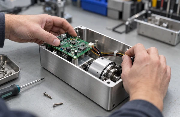
Use the first integrated build to answer questions that CAD and individual inspections cannot settle. Define what the pilot must prove before choosing the quantity. For one project, the priority may be cable routing and tool access; for another, it may be programming, sealing or test coverage.
During the pilot, record:
- The actual installation order and any temporary part removal
- Tool access for screws, press-fit items and connectors
- Cable routing, bend behaviour and strain relief
- Fastener type, torque requirement and locking method where needed
- Adhesive, thermal material or gasket placement
- Programming point and firmware identification
- Rework needed to make parts fit
- Assembly time observations when they affect tooling or workstation design
Photographs make a work instruction easier to follow, but they should not be the only definition. Link each photograph to the relevant part revision and label it as either an approved method or a trial.
Do not quietly absorb a pilot-build rework into production. If a hole must be enlarged, a cable rerouted or a bracket bent by hand, decide whether to change the design, add a controlled operation or reject the condition.
7. Inspect interfaces at the integration point
Incoming inspection should match the risk at final assembly. Measuring every available dimension wastes time; checking only supplier certificates can miss a poor fit.
For mechanical parts, inspect the datums and features that locate the PCBA, connectors, covers and mating hardware. Confirm finishes on grounding, sealing or cosmetic surfaces. For the PCBA, confirm the correct assembly revision, programmed version where applicable and any dimensions that affect enclosure fit. Check cable identity, pinout, length, connector orientation and strain relief before installation.
Industry standards can define part of the acceptance scope when the contract calls for them. IPC lists IPC-A-610 for electronic assembly acceptability and IPC J-STD-001 for soldered electrical and electronic assemblies. IPC/WHMA-A-620 addresses cable and wire harness requirements and acceptance. State the exact standard, revision, class and any customer-specific exceptions instead of writing “build to IPC” on a purchase order.
These standards do not replace a product test. A visually acceptable PCBA can still contain the wrong firmware, and an acceptable cable can still be too short for the intended route.
8. Define final assembly testing before the fixture is designed
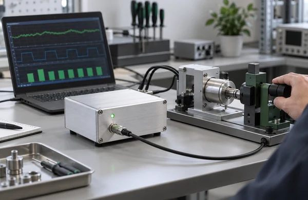
Write the test requirement around product behaviour. “Power on and check” is too vague for fixture design, quotation or failure analysis.
A final test plan may include:
- Unit identification and hardware/firmware revision check
- Safe power-up sequence, voltage and current limits
- Communication, sensor, control and output checks
- Connector and cable continuity where not covered earlier
- User-interface checks for buttons, indicators and displays
- Mechanical checks for movement, noise, latch or seal behaviour
- Inspection of labels, cosmetic surfaces and included accessories
- Test record, serial number and result retention
For each step, state the stimulus, expected result and allowed limits. Identify who supplies software, fixtures, mating cables and reference units. If the manufacturer must develop the fixture, agree on the fixture review and validation process before the build is scheduled.
A golden sample can help with appearance or test setup, but it does not replace controlled drawings and limits. Samples wear, get repaired and sometimes contain undocumented deviations.
9. Control substitutions and changes across the whole product
A substitution that looks local may have product-level effects. Before approving it, check fit, electrical behaviour, firmware compatibility, safety or regulatory impact, thermal load and availability of mating items.
Record:
- The proposed part and reason for change.
- The affected BOM lines, drawings, firmware and test instructions.
- Evidence used for the decision.
- Approval and effective build or serial number.
- Treatment of stock, work in progress and completed units.
Emergency approvals should still leave a record. An email can document a one-time decision if it identifies the exact product, revision, quantity and deviation. Transfer the decision into the controlled project record before the next build.
10. Prepare a quote package that matches the real scope
A quotation for separate parts does not cover an assembled and tested product unless that work is included in the scope. State where responsibility starts and ends.
Include:
- Prototype and expected follow-on quantities
- Product variants and the mix required in each build
- Sourcing model for mechanical parts, electronics and standard hardware
- Customer-supplied items and their expected delivery condition
- Assembly, programming and test work
- Required records, serialization and packaging
- Target delivery location and requested timing
- Approval route for questions, substitutions and deviations
Zenbot China reviews projects that combine mechanical parts, plastics, electronics, finishing and product assembly. The other manufacturing services page covers assembly, testing and packaging requests. The PCB and PCBA service covers PCB fabrication and electronic assembly. The final scope depends on the released files, quantities, inspection needs and test definition.
Build-ready handoff checklist
Before authorizing an integrated build, confirm that the package contains:
- One product part number, revision and top-level BOM
- Matching revisions for mechanical parts, PCBA, cables and firmware
- Controlled interface dimensions and mating-part references
- Assembly drawing or work instruction with a feasible installation order
- Approved sourcing and substitution rules
- Pilot-build findings resolved or listed as controlled deviations
- Incoming checks for fit-critical and revision-sensitive items
- Final test steps with limits, fixtures and record requirements
- Packaging, labels, accessories and shipment configuration
- Named contacts with authority to approve technical changes
Open the final archive after it is created. Check that the file list matches the release note and that superseded files are not mixed with production data.
Frequently asked questions
1. Is one BOM enough for mechanical parts, PCBA and final assembly?
Use one product-level BOM, but keep detailed subassembly BOMs where they are useful. The top-level BOM should identify the released revision of each mechanical, electronic, cable and firmware item. The PCBA BOM can then carry component-level sourcing detail without turning the product BOM into an unreadable list.
2. Who should own the final assembly drawing?
The project should name one owner for the released assembly definition. That may be the customer, design firm or manufacturing partner. Other teams can contribute information, but one approval route should control the drawing, BOM and work instruction used for the build.
3. Can a golden sample replace drawings and inspection limits?
No. A golden sample is useful for appearance comparison, fixture setup or a functional reference. It may contain wear, repairs or undocumented changes. Use it alongside controlled files and measurable acceptance limits.
4. When should firmware be frozen for a pilot build?
Release a named firmware version before units are programmed, and record the target hardware revision. Later updates are possible, but the build record must show what was installed in each unit and whether the change affects testing or compatibility.
5. Can mechanical parts and PCBAs come from different suppliers?
Yes, if the interfaces, revisions, delivery state and inspection responsibilities are controlled. Decide who checks fit before volume assembly and who owns problems that cross supplier boundaries. Sharing only nominal CAD files is rarely enough.
6. What should be included in a final product test?
Test the functions and interfaces that matter to the released product. State the input, expected result and limit for each step. Include hardware and firmware identification, required fixtures, serial-number records and the response to a failed unit.
Keep the product release tied together
Different suppliers may make the enclosure, PCBA and cables, but production still needs one product-level release. The top-level BOM identifies the versions that belong together. Interface drawings show how they fit, and the assembly and test plan defines the accepted unit.
Before requesting a quote, separate released files from work that still needs an engineering decision. Then send the product package for review with the quantities, sourcing plan, assembly scope and test requirements.