


How to Prepare a CNC Part for Machining: DFM Checks for Corners, Thin Walls, Deep Holes, and Threads
Before sending a CNC part for a quote, look at it from the machinist’s side. Where will the stock be held? Can a cutter reach each feature without the holder hitting a wall? Mark the dimensions that make the part fit. Pocket corners, thin walls, deep holes and threads deserve a second look; they often look simpler in CAD than they are at the machine.
Keep this CNC machining DFM checklist beside the current model and drawing. The right answer for a feature depends on the material, the machining route and how the finished part will be checked.
CNC machining DFM at a glance
| Check | Question to resolve | What to show the machining team |
|---|---|---|
| Function | Which faces, bores and threads control assembly or performance? | Mating parts, load direction, critical dimensions and inspection needs |
| Setup and access | Can tools reach the features, and where can the stock be held? | 3D model, intended reference faces and any surfaces that cannot take clamp marks |
| Corners and pockets | Can a practical cutter form the internal radii and pocket depth? | Mating-component clearance, pocket geometry and critical corner requirements |
| Thin features | Will walls or tabs remain supported during cutting and in use? | Material, wall height and thickness, open edges and functional loads |
| Holes and threads | Are depth, entry, exit, thread specification and access clear? | Hole and thread callouts, fastener or insert details and fit requirements |
| Tolerances and finish | Which features need close control, and in what finished condition? | Datums, tolerances, surface finish, coating and inspection method |
Zenbot’s CNC machining service covers milling and turning for metals and plastics. Tolerance and inspection requirements are reviewed against the actual part before they become quotation commitments.
1. Start with the part’s function and material
A bearing bore may locate a shaft; a shallow recess may exist only for appearance. Label those differences on the drawing. Otherwise, the machinist has to guess which surfaces deserve close control and which can change during the DFM review.
Check the part in its assembly. If a corner only provides clearance, a radius or local relief may be harmless. A sealing edge is different: its shape and finish need to be specified. Mark both kinds of feature so the machining team knows where it has room to suggest changes.
Name the material grade and stock condition if they are fixed. “Aluminum” or “plastic” alone leaves too much open: stiffness, machinability and thin-wall behavior vary. If the grade is undecided, describe the loads and operating conditions and ask for options. Zenbot lists material families on its service page; the grade, condition and traceability belong in the project review.
2. Check orientation, workholding and tool access
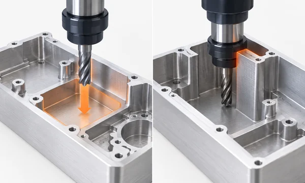
Look at the model as a block, plate or bar of stock. Pick a plausible clamping face and trace what can be cut from that position. If the part must be flipped, it needs a second way to locate it. Features made in separate setups may also need a clearly defined relationship on the drawing.
Inspect deep pockets, side openings, undercuts and features tucked behind tall walls. Even when a machine can orient the tool, the holder or fixture may block the approach. A narrow pocket may call for a long cutter that is more prone to deflection. Protolabs’ CNC design guide discusses these access problems in its DFM review.
Tell the machinist which faces cannot take clamp marks or handling blemishes. This matters most when every outer face is cosmetic. For a required second setup, agree on the locating faces and the feature relationships that will be inspected afterward.
3. Give internal corners and pockets a workable cutter path
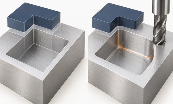
An end mill is round, so it leaves a radius in a pocket corner. If a square-cornered component must sit inside that pocket, check its actual clearance. A larger radius, a small corner relief or a change to the mating component may solve the fit. Keep a truly square corner as a special requirement only when the assembly calls for it.
A small radius calls for a small cutter. Deepen the pocket and that cutter may have to extend farther from its holder, making chatter or deflection more likely. Protolabs’ machining guidance covers both issues. Its published size limits describe its tooling and should not be copied into a Zenbot drawing.
The pocket floor needs its own review. Bottom-corner shape, flatness and surface texture can change the tool choice. Mark the faces that mate with another part; leave purely clearance surfaces at an agreed general requirement.
4. Review thin walls, tall ribs and unsupported tabs
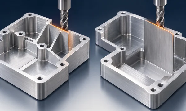
A thin wall can move under the cutter, spring back afterward or distort as surrounding stock is removed. Thickness alone tells only part of the story. A short wall tied in at both ends behaves differently from a tall wall with one free edge, even when both have the same thickness.
Trace where each wall gets its support. Note free edges, long spans and broad pocket floors. The remaining stock may support a feature during roughing, then stop supporting it during finishing. Protolabs’ DFM guide flags thin features for this reason; its numerical threshold applies to its own process.
If the thin wall is there to save weight or meet a stiffness target, say so. A thicker local section or a shorter unsupported span may help; changing the cutting sequence is another option. Which one makes sense depends on how the part fits and carries load.
5. Make holes and threads unambiguous
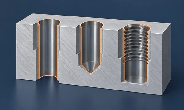
A hole’s purpose determines its callout. A fastener clearance hole, locating-pin bore, thread and fluid passage may look similar in a model but need different fits and inspection. Show the entry face, depth and distance from nearby edges. Say whether a through hole is allowed.
Deep holes give chips farther to travel out and often need a longer tool. If the opposite face may be opened, consider a through hole. For a blind threaded hole, show the usable thread depth separately from the total drilled depth so the tool has room to finish. Protolabs’ hole-design guide explains the difference between these features.
A modeled spiral does not replace a thread callout. Specify the thread system, size, pitch, usable depth and required gauge or fastener fit. Name any insert and its installation requirement. For a counterbore or countersink, check the actual screw head. A bore that locates a pin or bearing needs its fit and measurement method on the drawing as well.
6. Tie tolerances and finish to inspection
Put the tightest tolerances where fit, motion or sealing requires them. Blanket tight tolerances add machining and measurement work while giving the shop little clue about priority. Agree on a general tolerance for the remaining geometry.
Choose datums that match how the part locates in the assembly and how it can be measured. A bore controlled from an unrelated face may be difficult to inspect and may miss the relationship that matters. If the drawing uses geometric dimensioning and tolerancing (GD&T), apply it consistently. ASME Y14.5 defines the symbols and interpretation rules.
Say whether dimensions apply before or after finishing. Coatings and polishing can change the mating surface; blasting can change its texture. Mark areas that must stay uncoated and agree on a sample or acceptance criteria for visible faces. Zenbot lists finishing options on its CNC page, with compatibility reviewed for each job.
The inspection request should match the drawing. For example, if a bore is specified after coating, the measurement plan should say so. Protolabs’ tolerance guidance discusses the cost of over-constraining non-critical features.
An example: a machined aluminum electronics housing
Consider an aluminum housing for a small circuit board. It has a recessed seat, four mounting holes and a connector opening. This is an example, not a customer part.
The board seat and connector position matter to assembly. The pocket’s square internal corners came from tracing the board outline in CAD; the board itself has clearance at those corners. The designer can add a cutter-friendly radius without moving the board. One side wall stands free after the pocket is cut, so its support during finishing needs review. Of the four mounting holes, three only clear screws; the fourth locates the housing and needs a different callout.
The revised drawing controls the board seat, locating hole and connector relationship. The other pocket walls remain clearance surfaces. That gives the machinist a clearer setup and inspection target.
What to send for a CNC DFM review
Send a current 3D CAD model and a matching drawing. The drawing should carry the part number and revision, material and finish, critical dimensions and datums, thread callouts, and any inspection or cosmetic requirements. Add the order quantity, mating-part information and whether this is a prototype or repeat build. Write “open for review” beside undecided requirements instead of leaving the supplier to infer them.
Zenbot’s manufacturing RFQ checklist covers the broader purchasing package. If the prototype process is still open, use the CNC machining vs. 3D printing guide to decide what the first part needs to prove.
Frequently asked questions
1. Do all internal corners on a CNC part need a radius?
An end mill leaves a radius in a pocket’s vertical inside corners. The radius depends on the cutter and how far it must reach. If a mating part has a square corner, see whether a small relief will give it clearance. If it will not, ask the machinist about another process.
2. What is the minimum wall thickness for CNC machining?
There is no useful single minimum. A short, supported wall behaves differently from a tall wall with a free edge. Material and clamping matter too, so send the model for review before designing around a number from a general guide.
3. Should I put the tightest tolerance on every feature?
No. Put close tolerances on the features that control fit, motion or sealing. Use an agreed general tolerance elsewhere. The drawing should also show how the closely controlled features will be located and measured.
4. Is a STEP file enough for a CNC quote?
A STEP file shows the shape, but it may say nothing about material grade, threads or the finish that matters to fit. Send a matching drawing and a short RFQ note with the remaining requirements.
5. Can features on several sides be machined in one setup?
Sometimes. The machine may be able to turn the part, but the holder still needs clearance and the stock needs a secure place to sit. If a second setup is needed, mark the locating faces and the dimensions that must stay related across setups.
6. What belongs in a blind threaded hole callout?
State the thread system, size, pitch and usable thread depth. Give the total drilled depth separately, and identify the mating fastener or insert if it affects fit. A modeled thread alone does not tell the shop where full threads must end.
7. Should dimensions be checked before or after coating?
State the condition on the drawing. If a bore or mating face has a final-size requirement, specify inspection after finishing and mark any surfaces that must stay uncoated. Otherwise, a bare part may pass inspection and still be too tight after coating.
Before requesting a quote
Check that the model and drawing have the same revision. Mark the functional interfaces, material, finishing condition and any DFM question still open. The machinist can then assess the disputed features against the actual files.
Zenbot reviews part geometry and requirements through its CNC machining service. Send the files through the quote page for a project-specific assessment.