


Injection Molding DFM Checklist: Wall Thickness, Draft, Ribs, and Gate Location
Use this injection molding DFM checklist before approving tooling for a plastic part. Check six things: the selected resin and wall thickness, the mold opening direction and draft, ribs and bosses, likely gate and weld-line locations, ejection, and the dimensions that determine fit. A 3D model can be geometrically complete while leaving several of these manufacturing decisions unresolved.
An injection molding design-for-manufacturing (DFM) review is a discussion around the actual part, material and tool—not a pass/fail score from a generic checklist. Use the checks below to mark what is fixed, what can change, and what the molder must evaluate before cutting the tool.
Injection molding DFM at a glance
| Design area | Question to answer before tooling | What to put in the review package |
|---|---|---|
| Function and fit | Which surfaces, holes and interfaces control assembly? | Mating parts, critical dimensions, datums and inspection requirements |
| Material and walls | Can the chosen resin fill the thin areas and cool without avoidable thick sections? | Resin grade or required properties, nominal wall and local thickness changes |
| Mold opening | Can the part release in the proposed pull direction? | Drafted CAD model, intended visible faces, possible parting-line limits and undercuts |
| Ribs and bosses | Do reinforcing features create thick junctions or block tool access? | Rib and boss geometry, screw or insert specifications and load requirements |
| Flow and gates | Where can material enter without putting a gate mark or weld line on a sensitive feature? | Cosmetic zones, load-bearing areas and any prohibited gate locations |
| Ejection and acceptance | Where can the tool push on the part, and how will the finished part be checked? | Acceptable mark locations, inspection method and assembly test |
The table identifies questions, not universal dimensions. Resin behavior, surface texture, part depth, tool design and production quantity can change the answer. Zenbot’s injection molding service describes prototype and production tooling paths; the route for an individual part is confirmed after engineering review.
1. Define the part’s job before adjusting the geometry
Start with the surfaces that locate the part and the features that carry a load, seal, snap, fasten or align. Put mating parts into the CAD assembly. Mark the faces customers will see and the faces that can accept a gate vestige, parting line or ejector mark.
Then separate requirements from preferences. A hole that locates a connector may need a controlled position; an outer wall that touches nothing may not. Identify which dimensions apply to the molded part after cooling and which are merely nominal CAD geometry. This gives the tool designer room to manage shrinkage and process variation without losing the interfaces that matter.
If material is still open, state the required performance and operating conditions rather than silently choosing a familiar resin. A change in resin can alter flow, shrinkage, stiffness and surface appearance. The proposed resin grade should be reviewed together with the part geometry and acceptance criteria.
2. Review wall thickness and transitions
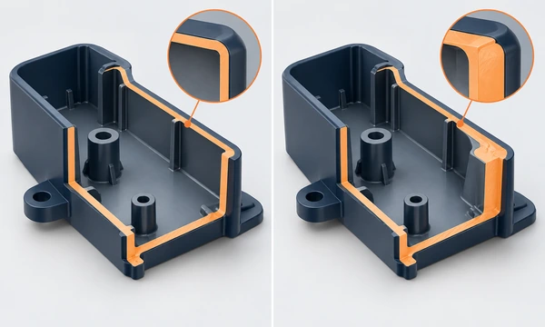
Follow the part section by section. Look for very thin flow paths, sudden changes in thickness, and solid masses behind visible faces. Thick regions cool differently from thin ones and can contribute to sink or distortion; thin regions may be difficult to fill. Protolabs’ wall-thickness guidance explains why nominal thickness and local transitions belong in the moldability review.
Aim for a wall pattern that suits the selected material and function. Where a thicker area is needed for a screw, load path or interface, ask whether a cored section with ribs can do the job. Where thickness must change, review the transition rather than treating the two wall values independently.
Do not copy a single wall-thickness number from another resin or supplier’s guide into every drawing. Recommended ranges depend on the resin, flow length, part size, geometry and tooling. Record the proposed nominal wall, then have the molder assess the thin and thick regions for this part.
3. Check pull direction, draft and undercuts together
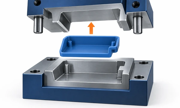
Choose a likely mold opening direction and inspect every face in that view. A wall that is parallel to the pull direction may need draft to release without dragging. Deep features and textured faces can change the draft requirement. Protolabs’ draft guidance treats draft as part of ejection and surface quality, not a number to add at the end.
Next, look for features that prevent a straight pull: a side hole, a reverse lip or a clip trapped behind the mold steel. They may call for a design change, a side action or another tooling method. Those options affect tool complexity and should be reviewed before the geometry is frozen. Autodesk’s moldability analysis checks draft, nominal wall thickness and undercuts as related concerns.
Place the likely parting line on the model. Ask whether it crosses a seal, a visible face or a dimension that controls fit. A parting line is a tooling decision, but the product requirements should tell the tool designer where it would be unacceptable.
4. Inspect ribs, bosses and inserts as one assembly
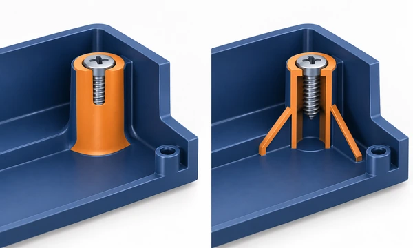
Ribs can stiffen a wall without turning it into a solid block. They can also create a thick junction where they meet the main wall. Inspect the rib base, neighboring wall and visible opposite face together, especially if sink or appearance matters. Protolabs’ design essentials discusses rib-to-wall relationships as a way to limit such defects; its figures are general guidance, not Zenbot’s acceptance limits.
For every screw boss, check the screw or insert specification, the surrounding wall, the load direction and access during assembly. A boss that fits the screw in CAD may still be too close to a wall for the driver, or may put unnecessary mass behind a cosmetic surface. If the design uses a metal insert or overmolded component, define how it is located and what movement or pull-out performance is required. The process and validation method must be agreed for that part.
5. Agree on gate and weld-line constraints
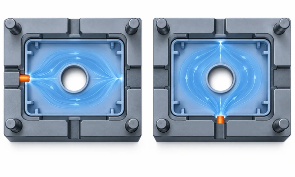
The gate is where molten material enters the cavity. Its position influences filling, visible gate marks, air traps and where flow fronts meet. A weld line can be both a cosmetic concern and a concern at a loaded feature. Autodesk’s gate-location guidance advises considering load-bearing areas, appearance and likely weld-line positions together.
The product team does not need to specify a final gate type without a tool review. It should identify constraints clearly:
- Faces where a gate vestige is acceptable or prohibited
- Areas where a weld line would interfere with appearance, sealing or strength
- Holes, windows and inserts around which the flow may split
- Surfaces that must remain available for labeling, coating or assembly
The molder can then compare feasible locations against the actual resin and mold layout. A computer prediction is useful for comparing options, but the selected position also has to be practical for the tool and acceptable for the product.
6. Plan ejection and cosmetic acceptance
The part must leave the mold after it cools. Identify surfaces that can take ejector contact and surfaces where a mark would be rejected. Deep ribs, thin walls and an awkward pull direction can make ejection harder even when the part fills. Protolabs’ ejector-pin guidance describes why pin placement should be reviewed before the order is finalized.
Do the same for texture, gloss, color, flash and parting-line appearance. “Cosmetic quality” is too broad to inspect consistently. Mark the visible faces, describe what is acceptable, and agree on samples or inspection criteria where appearance is important. Texture, resin and draft should be reviewed together; changing one late can affect the others.
A short example: a molded cover with four screw bosses
Consider a cover that fastens to an electronics base. This is an illustrative design, not a Zenbot customer part. The cover has a visible outer face, four internal bosses and a connector opening.
The first review marks the outer face as cosmetic and the screw pattern as a functional interface. The CAD section then reveals extra material where two bosses meet the wall. The team can review a cored boss and reinforcing ribs instead of leaving a solid junction. The tool designer checks draft on the sidewalls, a pull direction that releases the connector opening, and gate and ejector positions that avoid the visible face. Finally, the drawing specifies the screw-interface dimensions and an assembly check with the actual base.
There may be more than one workable design. The useful outcome is a recorded decision on each risk before the tool is cut.
What to send for a DFM review
Send a current 3D CAD model and a 2D drawing that identifies the critical dimensions and datums. Add the intended resin grade or performance requirements, expected quantity, surface finish, color, cosmetic zones, screw or insert details, mating parts, inspection needs and target schedule. If the part is intended for a regulated application, state the applicable requirements and evidence expected; do not assume a material name or process alone satisfies them.
Mark open decisions plainly. For example, “gate position open; no gate vestige on front face” gives the tool designer a useful constraint without inventing a solution. The broader manufacturing RFQ checklist covers the files and commercial scope that should accompany the design.
Frequently asked questions
1. Is there one wall thickness that works for every injection molded part?
No. Start with the selected resin, part size and functional requirements, then review the nominal wall and local transitions with the molder. Supplier guidelines are starting points; they do not guarantee that a specific geometry will fill or cool as intended.
2. Can a visible wall have no draft?
It may require a different tool approach or a different appearance decision. Draft depends on depth, texture, resin and ejection. Flag the visible face and discuss the trade-off before treating zero draft as a fixed requirement.
3. Who chooses the final gate location?
The tool designer proposes a feasible location using the part geometry, resin and mold plan. The product team should define where a mark or weld line would be unacceptable, then review the proposal against appearance and function.
4. Should prototype and production tooling use the same part design?
Keep the product’s required interfaces consistent, but review the design again when the tool, resin, quantity or finish changes. Zenbot lists aluminum prototype and steel production tooling as possible paths. The appropriate path and any design changes depend on the project review.
Before releasing the tool
Record the approved resin, model and drawing revision, critical interfaces, open or resolved DFM issues, visible-face requirements and the agreed inspection plan. If the part still has a disputed gate, draft, undercut or boss design, resolve it while the change is still a design decision.
Zenbot can review the part and tooling requirements through its injection molding service. When the files and acceptance criteria are ready, send them through the quote page for a project-specific review.