

Sheet Metal vs. CNC Machining for Electronics Enclosures: Which Process Fits Your Design?
Choose sheet metal when the enclosure can be cut from a flat blank and formed into a useful shell. Choose CNC machining when the design needs material left in specific places: a deep cavity, a substantial mounting feature, or closely related machined faces. Some enclosures use both. The decision comes down to the part’s geometry and the interfaces that must work after assembly, not a fixed order quantity.
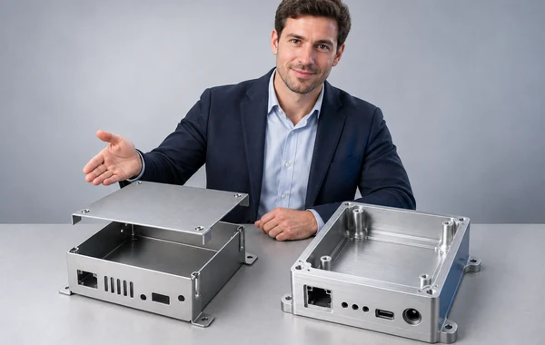
For an electronics enclosure, sketch the PCB, connectors, lid, fasteners and any gasket before choosing a process. A box can look simple until a connector must line up with a board edge or a cover must compress a seal evenly. This guide compares the two routes against those details. Zenbot offers both sheet metal fabrication and CNC machining, with the material, finish and inspection scope reviewed for each project.
Sheet metal vs. CNC machining at a glance
| Design question | Sheet metal is a sensible starting point when… | CNC machining is a sensible starting point when… |
|---|---|---|
| Overall shape | Flat panels, bends and joined pieces form the shell. | Pockets, thick sections or sculpted surfaces are part of the housing. |
| Wall and mounting features | A chosen sheet gauge works, with separate inserts or brackets where needed. | Local bosses, bores or mounting lands need to be cut from the same piece. |
| Critical fit | Important relationships can be controlled after forming and assembly. | Several critical faces or bores must be machined relative to one setup or datum scheme. |
| Access and assembly | Bending, welding or hardware installation can reach the intended features. | Cutters can reach the pockets and the stock can be held through the required setups. |
| Quantity and cost | The finished cost of cutting, forming, joining and finishing is acceptable. | Stock, machine time, setups and finishing are acceptable for the required quantity. |
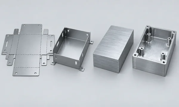
These are starting points for a design review, not promises about price or tolerance. Protolabs’ guide to electronic enclosure manufacturing also treats geometry, material and production stage as separate parts of the choice. Its lead times and quantity examples describe its own service, so they should not be used as Zenbot quote thresholds.
Start with the interfaces, not the box outline
Mark what the enclosure actually has to locate. A PCB may need four standoffs, but only one connector opening may control the board’s position against the outside wall. A lid may need a flat sealing land. Those features deserve dimensions and datums; the remaining outer edges may only need enough clearance to close the box.
Now look at how the enclosure will be opened and built. Can an installer reach the screws? Is there room to insert a press-fit fastener before a bend closes access? Will a cable or fan need a cutout in a formed wall? The answers often expose a poor process choice earlier than a price estimate does.
Send the same functional requirements with either quote request. If one supplier is quoting a powder-coated sheet metal assembly with installed hardware and the other is quoting a bare machined block, the prices do not describe the same deliverable.
Where sheet metal works well
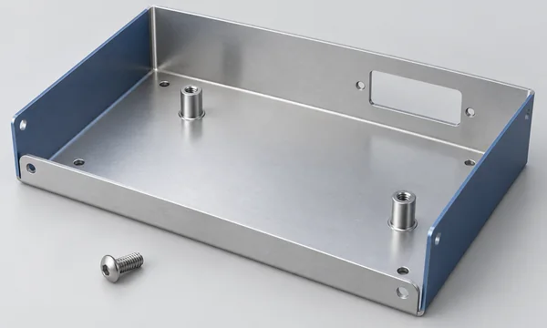
A folded shell suits an enclosure made mostly from panels of one gauge. Laser cutting or punching creates the blank and openings; bending gives it depth. Welding or removable fasteners can join the pieces when one formed part will not do the job. Zenbot’s sheet metal page lists cutting, bending, welding and hardware insertion as processes to review.
The design still needs room for the forming tools. A flange that is too short for the chosen setup, or a connector hole close to a bend, can become a production problem. The sheet stretches near the bend, which may distort nearby features. Protolabs’ sheet metal design guidelines explain the effect and give distances for its own tooling. Use those figures as review prompts, not as Zenbot design rules.
If the enclosure is a folded shell with a removable cover, put the bend radii, seams, installed hardware and cover fit on the drawing. Zenbot’s sheet metal enclosure DFM guide goes deeper into hole placement, bend relief and fastener access.
Where CNC machining makes sense
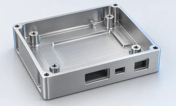
Machining starts with stock and removes material. That gives the designer room to leave thicker material around a bearing seat, a threaded boss or a connector face while cutting a cavity elsewhere. A single machined part can also put several functional features in one datum scheme. Those are useful reasons to investigate CNC; they do not mean every wall or pocket should be tightly toleranced.
The cutter must still reach the geometry. Deep pockets, narrow slots and square internal corners can call for longer or smaller tools. The workpiece may also need more than one setup to expose all sides. Protolabs’ machining guide discusses those limits. Zenbot’s CNC machining DFM checklist shows how to review tool access, pocket corners and thin walls before sending a quote.
A machined enclosure may be the clearer choice when a board seat, connector face and mounting bore must stay closely related. It may be unnecessary when the part is mostly empty space surrounded by broad, uniform walls. Compare the actual material removal and setup plan with a folded alternative.
A mixed design may solve the awkward feature
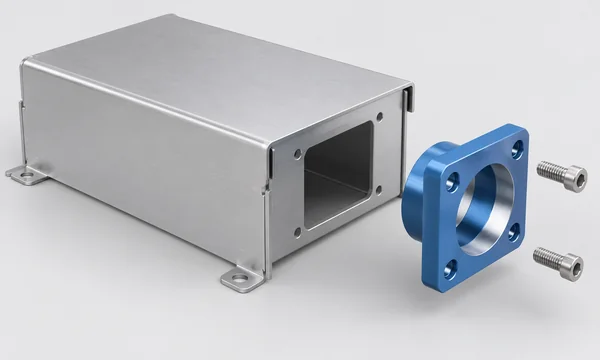
Sometimes a sheet metal shell is right for most of the box, but one feature asks too much of the formed part. A small machined bracket or insert can carry a precise bore or local mounting surface. The shell then supplies the broad panels and cutouts. Zenbot’s service pages describe these processes as related routes; Protolabs’ fabricated-assembly guidance also identifies secondary machining for features that are difficult to form or cut in sheet.
The joint needs its own drawing. Specify how the insert locates, how it is attached, and which dimensions are checked after assembly. Adding a machined piece is not a shortcut if it creates an unmeasurable tolerance stack or blocks the installer from reaching a fastener.
Compare the finished enclosure, not the raw part
There is no useful rule that says sheet metal is cheaper above a certain quantity or CNC is faster below it. A folded enclosure might need multiple blanks, welds, inserted hardware and a cosmetic finish. A machined one might need expensive stock, a long pocketing cycle or several setups. Revision risk matters too: moving a connector opening is a different change from redesigning a formed corner.
Ask for the same quantity bands and finished condition on both quotes. Include installed hardware, coating or anodizing, assembly and inspection in the scope. If a prototype will be followed by repeat builds, tell the supplier which dimensions and materials must stay fixed between revisions. A price comparison then has a real engineering basis.
Finish can alter the answer. Zenbot lists powder coating and other finishes for sheet metal, and anodizing, blasting and related options for CNC parts. Compatibility, masking, texture and appearance are project-specific. Mark any electrical contact surface, sealing land or close-fitting bore that needs special treatment. Do not assume an enclosure will meet a sealing or grounding requirement simply because it is made from metal.
Example: a compact controller housing
Consider a controller with one PCB, two cable connectors and a removable lid. The board mounts on four points. A display opening and the connector positions matter to the assembly; the back and side walls mainly protect the board. This is a design example, not a Zenbot customer project.
One route is a folded sheet metal shell with an inserted standoff pattern and a separate lid. The designer must check bend access, connector cutouts near corners and the finished relationship between the lid and board. Another route is a machined base with a board pocket and integral mounting features. That route needs a cutter-access review and a drawing that distinguishes the important mating surfaces from clearance walls.
If only one connector face needs close control, a folded shell with a small machined interface piece may be enough. The best route depends on the actual board and mating parts. A comparison quote should include the same finish, hardware and inspection request for all three concepts.
What to send for a fair process comparison
- A current 3D model and a drawing with part numbers and revisions. Show the PCB envelope, connector keep-outs, lid and any mating components.
- Material and finish requirements, or the functional requirements if the grade is open for review. State any masking, appearance or corrosion requirement.
- Critical datums and dimensions. Mark the connector alignment, mounting pattern and sealing surfaces that must be checked after finishing or assembly.
- Quantity bands, prototype purpose and whether the first design is expected to become a repeat order. Include required hardware and assembly scope.
- Open questions. If a seam, bend, boss or insert can change, say so rather than making the supplier infer design freedom from the CAD file.
Zenbot’s manufacturing RFQ checklist covers the broader file package. A useful request asks the supplier to compare both routes against the same functional drawing and identify any features that need redesign.
Frequently asked questions
1. Is sheet metal always cheaper than CNC machining for an enclosure?
No. Compare the finished assembly at the quantity you need. Bends, welds, hardware and coating add work to a sheet metal route; stock removal and extra setups add work to a machined route. A bare-part quote will not settle the question.
2. Can a sheet metal enclosure hold a precise connector position?
It may, but the drawing has to say what the connector is located from and when it will be measured. A feature near a bend may distort during forming. If the relationship is especially tight, ask whether the opening should move, be cut after forming, or use a separate machined interface.
3. Is a machined enclosure automatically better for sealing?
No. A continuous machined land can help define a gasket seat, but sealing also depends on the joint, fastener layout, finish and validation method. State the environment and acceptance test before choosing the process.
4. Can one enclosure combine sheet metal and CNC parts?
Yes. A formed shell can carry a machined bracket, insert or mounting face. Define the joint and inspection points; otherwise a precise insert may still end up in the wrong position after assembly.
5. Which route is easier to revise after the first prototype?
It depends on the change. Moving a flat cutout may be straightforward, while changing a bend can affect the blank and neighboring features. A CNC change may need a new setup or tool path. Tell the supplier which features are still experimental and ask how each revision affects the process plan.
6. What files are needed to quote both options?
Send the same model, drawing, quantity bands and finish requirements for each option. Add the PCB and connector envelopes, critical dimensions, installed hardware and assembly expectations. Mark any feature the supplier is free to redesign.
7. Should I specify an aluminum grade before choosing the process?
If the grade is fixed by strength, forming, finish or procurement, specify it. If not, state those requirements and ask for material options. A formable sheet alloy and a readily machined stock grade may not be the same choice; Zenbot reviews exact grade, temper and availability for each job.
Next step
Put the critical interfaces on one drawing, then request the folded, machined or mixed route that appears plausible. If two routes remain credible, send both concepts through Zenbot’s quote page and ask for a DFM review against the same finished-part requirements.