

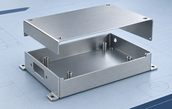
Sheet Metal Enclosure Design for Manufacturing: Bends, Holes, and Fasteners
A flat pattern can look ready for cutting while the finished enclosure still has a problem: a connector clashes with a wall, a hole distorts during bending, or a press tool cannot reach a standoff. In sheet metal enclosure design, start with the assembled part. What has to fit? What must remain accessible? Which dimensions matter after forming and finishing?
The answers depend on the chosen material and thickness, the tooling, and the order of operations. A bend radius or hole spacing copied from another job is a useful question to ask the fabricator, not a specification to adopt without checking.
Sheet metal enclosure DFM at a glance
| Design area | Check in the formed assembly | What can go wrong |
|---|---|---|
| Bends and corners | Radius, flange length, relief, and bend sequence | The blank cuts correctly but cracks, distorts, or blocks a later bend. |
| Holes and cutouts | Position and shape after bending | A hole near a bend moves or a narrow wall loses stiffness. |
| Fasteners | Sheet compatibility, hole size, edge distance, and press access | The specified hardware cannot be installed. |
| Assembly | Lid movement, board clearance, tool access, and cable path | Parts fit individually but cannot be assembled or serviced. |
| Finish and inspection | Coated and masked faces; dimensions measured on the finished part | A good-looking enclosure fails a fit or contact requirement. |
1. Start with the enclosure’s functional interfaces
Put the mounting surface, lid, connectors, board supports, and mating parts in the same assembly model. That view exposes conflicts a flat drawing hides. A connector may clear its cutout yet leave no room to plug in a cable; a screw may line up with its hole but sit too close to a wall for a driver.
Dimension the features that control those interfaces on a drawing of the formed part. If a connector opening must align with a fixed printed circuit board assembly (PCBA), it may need closer control than an outer edge that touches nothing. State the inspection datum and when the dimension is measured. Tightening every edge to the same tolerance adds work without necessarily improving the fit.
For an enclosure carrying a PCBA, look at connector reach, board clearance, standoff positions, screw access, and the route for removing the board. Zenbot’s PCBA service covers related assembly work; the mechanical interfaces still have to be defined for the particular product.
2. Choose bend geometry with the material and tooling
Choose the material grade and nominal thickness before approving a flat pattern. The inside bend radius, bend allowance, and relief change the blank size and the final dimensions. CAD can calculate a pattern, but it calculates from the rules entered. Autodesk’s sheet metal rule reference lists thickness, K-factor, bend radius, and relief as configurable inputs. The K-factor describes where the neutral axis lies relative to the material thickness.
Before release, walk through the planned bends with the fabricator:
- Can the tooling reach each bend in the intended sequence?
- Is each flange long enough for the selected tool to form it?
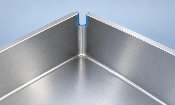
- Where two bends meet, does the corner need relief to prevent tearing or overlap?
- Does the folded model show the right bend directions and finished inside dimensions?
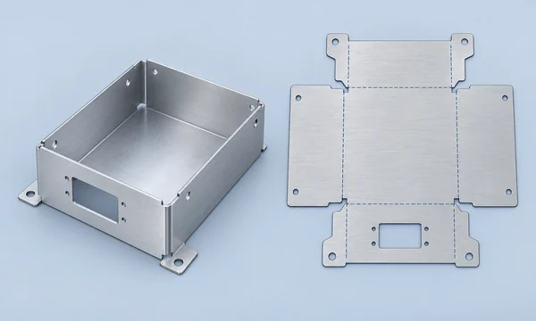
Corner relief should solve a forming problem while leaving enough material for the part’s function and appearance. Look at the same corner in the folded model and flat pattern; each view answers a different question. Autodesk’s flat-pattern guidance describes the information carried by a manufacturing flat pattern.
3. Check holes and cutouts in the formed part
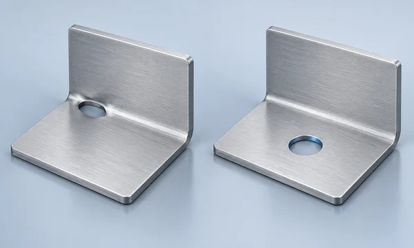
A hole beside a bend may come out oval or miss its target position. A large connector opening can leave a narrow strip that twists during forming. If moving the feature would break the product layout, ask whether moving the bend, adding relief, or making the feature in a later operation would work better.
Protolabs’ sheet metal design guidance gives examples of feature placement near bends. Its numerical limits describe that supplier’s service. For a Zenbot project, the material, thickness, tooling, and required finished position need their own review.
| Feature | First question | Possible response |
|---|---|---|
| Mounting hole near a bend | Where will the hole land after forming, and how much material remains around it? | Move the hole or bend, or use another operation. |
| Connector cutout on a narrow wall | Will the wall form cleanly and leave room for the connector? | Change the opening or wall arrangement. |
| Countersunk hole | Can this sheet support the countersink and screw head? | Change the screw head or use suitable installed hardware. |
| Visible opening | Will forming or finishing distort its edge? | Revise its position, shape, or appearance requirement. |
For a hole that locates a mating part, specify its required position on the finished enclosure. The distance from the bend is then a process decision to settle with the fabricator, not the only dimension that matters.
4. Design the fastener and its installation together
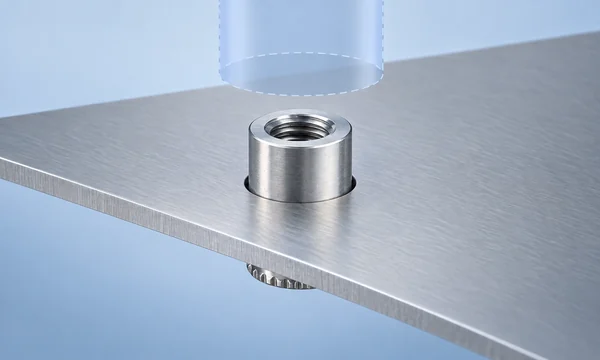
A self-clinching nut or standoff may be right for a thin panel, but selecting the part number is only half the job. Check the manufacturer’s sheet material and thickness range, mounting hole, edge distance, and installation side. PennEngineering’s self-clinching fastener handbook also covers installation near bends and the order of finishing operations.
Then give the press a path to the hole. In a CAD assembly, a standoff can appear to fit perfectly even though a formed wall blocks the installation tool. The drawing or controlled bill of materials should identify the part number, quantity, location, and installation side.
Coating needs the same attention. Mark threads or contact surfaces that must stay clear, and follow the fastener manufacturer’s guidance on installation and finishing order. If pressing the hardware is impractical, compare a rivet nut, welded nut, separate bracket, or different assembly layout.
5. Review joining, finish, and service access
Trace the assembly sequence through the model. Can the lid slide or lower into place after the connectors and hardware are installed? Can a screwdriver reach the last fastener? If the enclosure has welded parts, is there room for the tool and for subsequent finishing work? The finished product should also open in the way it will be serviced.
Mark visible faces, coating and masking areas, and surfaces needed for grounding or electrical contact. If coating changes a fit, define the dimension on the finished part. Weather sealing and electrical shielding require their own design and validation; neither follows automatically from a sheet metal fabrication process.
Zenbot’s sheet metal fabrication service lists cutting, bending, welding, and hardware insertion. Which of those processes belongs in a particular enclosure depends on its drawing, material, quantity, and finish.
6. Define how the finished enclosure will be accepted
A drawing is most useful when it says which dimensions control function and where to measure them. A mounting pattern, for example, may need to be checked from the panel face that contacts the machine. A dimension spanning several bends should say whether it applies after forming, joining, or coating.
Agree on the first-article checks before production. Depending on the design, those may include formed dimensions, fastener fit, lid closure, connector alignment, visible finish, and an assembly trial with the mating parts. There is little value in a long inspection list if it misses the feature that actually locates the product.
Example: a small electronics enclosure
Consider a two-piece enclosure with a PCBA, removable lid, side connector, and four self-clinching standoffs. This is an illustrative design, not a Zenbot customer project. Put the board and connector into the folded model first. Check the connector’s clearance through the wall, then make sure the lid and board can both be removed without a collision.
Next, examine the base bends and corner relief against the connector opening and mounting holes. Check each standoff’s specified hole, edge distance, installation side, and press access. Finally, mark the mounting face and connector opening as inspection interfaces. The result may call for a moved standoff or a revised wall. The model and the manufacturing route should decide which change makes sense.
What to send for a design-for-manufacturing review
Send the folded 3D model and a 2D drawing that identifies the important formed dimensions. Include material grade and thickness, installed hardware, joining and finish requirements, mating parts, quantity, and inspection needs. If you send a flat pattern, say whether it is a design reference or an approved manufacturing file.
Zenbot’s manufacturing RFQ checklist covers the wider quotation package. The points above are the enclosure decisions a fabricator needs to review before using that package to plan the work.
Frequently asked questions
1. Is one minimum bend radius safe for every sheet metal enclosure?
No. Material grade and temper, thickness, bend direction, tooling, and the required appearance or strength all affect the choice. Treat the CAD default as an assumption until the fabricator checks it.
2. How close can a hole be to a bend?
First define where the hole must end up on the formed part. The acceptable spacing then depends on its function, the material, and the bending process. A critical hole may need a new location or a secondary operation.
3. Can any self-clinching fastener be used in thin sheet metal?
No. Check the data for the exact part number against the sheet material and thickness, mounting hole, edge distance, and tool access. Similar-looking nuts and studs are not automatically interchangeable.
4. Is a flat DXF sufficient to manufacture an enclosure?
A DXF describes cut geometry. The fabricator also needs the formed shape, bend directions, finished dimensions, hardware, joining, and finish requirements. Agree on who creates and approves the production flat pattern.
5. When should I ask for a fabrication review?
Before locking the design, especially if bends intersect, holes sit near bends, or hardware is close to an edge. A fixed board or connector is another good reason to ask early. Zenbot’s manufacturing quote page accepts the project files needed for a specific review.
Before releasing the cutting file
Check the formed assembly and its inspection drawing alongside the flat pattern. If a hole, fastener, or lid movement is still uncertain, resolve it before calling the blank final. For a project review, see Zenbot’s sheet metal fabrication service and send the files through the manufacturing quote page.