


Custom Aluminum Extrusion Design: What to Check Before Making the Die
Before making a custom aluminum extrusion die, agree the profile cross-section, alloy and temper, extrusion tolerances and features added after extrusion. Mark the dimensions and surfaces that matter in the finished assembly. Include the cut length, finishing route and sample-approval requirements in the same review.
Zenbot’s casting, extrusion and supporting services include custom and standard aluminum profile requests, subject to die and alloy review. Use this guide to prepare a request for quotation (RFQ) and settle the design before authorizing tooling.
Custom aluminum extrusion design checklist
| Review item | What to show in the drawing or RFQ | Decision to settle |
|---|---|---|
| Profile geometry | A dimensioned cross-section, wall sections, cavities and functional grooves. | Which features belong in the extrusion, and which need later operations? |
| Material condition | Required alloy, temper and material documentation. | Does the proposed material and processing route meet the design requirements? |
| Dimensions and shape | Section dimensions, length, straightness, twist and the relevant datums. | What must be accepted at the extrusion stage and at the finished-part stage? |
| Secondary operations | Cut ends, holes, pockets, threads and deburring requirements. | How will the part be held, machined and inspected? |
| Finish and assembly | Visible faces, mating parts, coated surfaces and masked areas. | How will the finished interfaces and appearance be approved? |
| Tooling and order plan | Initial quantity, repeat orders, tooling terms and sample requirements. | What is included in the quote and required before the order proceeds? |
Review the section drawing and the finished-part drawing together before releasing the die.
What the extrusion die will produce
Conventional aluminum extrusion forms a repeated cross-section along the profile’s length. A heated billet is pushed through a die that creates the section. Hydro describes the process in its custom extrusion overview.
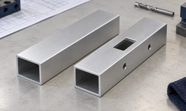
A continuous guide groove can be part of that section. A connector window at one position along a housing needs a separate manufacturing step. Identify both on the drawing so the supplier can quote the profile and its later operations together.
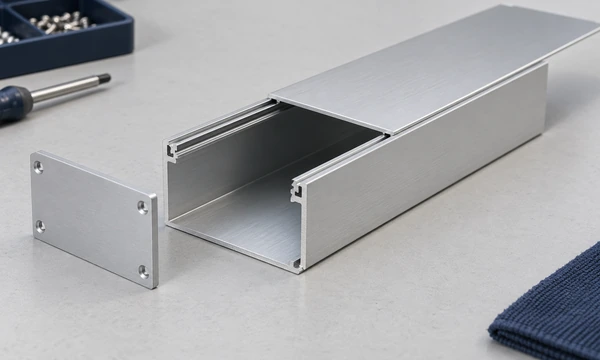
For an enclosure, show the finished length and the end-cap interface as well as the cross-section. If several product lengths share a section, provide a separate finished-part drawing for each length. Keep the common profile revision identifiable.
The Aluminum Extruders Council (AEC) discusses integrating functions into extruded profiles. Choose those functions from the assembly requirements: a board guide, mounting interface or sliding cover groove needs defined mating geometry and acceptance checks.
Review walls, transitions and corners
Balanced wall sections and smooth transitions are useful starting points for a profile review. AEC’s extrusion design tips recommend uniform walls where practical and rounded transitions at changes in thickness.
Mark the thinnest walls and the junctions where substantial material meets a thin section. Explain why each is needed. This gives the extruder a basis for proposing changes while preserving the part’s function.
There is no universal minimum wall thickness for every custom profile. Feasibility depends on the section, material and available tooling and equipment. Have the supplier review the actual geometry before adding a minimum value to the drawing.
Where a corner must clear a mating part, dimension the required clearance or relief. Replace a zero-radius CAD corner with an agreed radius or relief that clears the mating part, then verify the fit.
Discuss hollow sections and difficult openings early
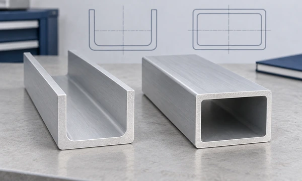
AEC’s profile shape guidance describes extrusion shapes as solid, hollow or semi-hollow. A fully enclosed void is a hollow feature; classification of a partially enclosed void can require an extruder’s assessment. Include a clear section view when requesting that review.
Ask about narrow openings, deep channels and slender features in the die. AEC’s key design considerations discuss deep, narrow die tongues and the overall profile envelope. These features warrant review before die manufacture.
Provide the overall section dimensions. The supplier may also use the circumscribing circle diameter, or CCD: the diameter of the smallest circle that encloses the cross-section. Have the supplier confirm equipment fit for the complete section and alloy.
If an internal channel must be cleaned, coated or machined later, show the access requirement now. A cavity that meets the assembly concept also needs a workable downstream process.
Specify the alloy and temper
Write the required alloy and temper on the controlled drawing. If material selection is open, provide the service loads, environment and planned joining and finishing operations for review.
Ask the supplier to confirm the material condition of the supplied profile and the documents included with the order. If welding or other thermal operations are planned, include them in the material review.
Keep an approved material change visible in the drawing and purchase specification. For repeat orders, retain the same identification and documentation requirements unless engineering approves a revision.
Separate section dimensions from finished-part tolerances
Profile width and groove spacing describe the cross-section. Straightness and twist describe behavior over a length. A machined hole position or end-cap seating face introduces another set of requirements.
AEC’s extrusion tolerance guidance explains that industry tolerance tables and more specific component requirements need discussion between the designer and extruder. Ask which tolerance basis, standard and revision the quotation uses, and list any agreed exceptions.
For the finished component, define:
- The surfaces or features used as datums.
- The finished length and cut-end requirements.
- Straightness, twist or flatness where they affect assembly.
- Hole and machined-feature locations relative to the agreed datums.
- Which dimensions apply after finishing.
Agree the measurement conditions as well. A long, flexible section can behave differently when freely supported, clamped or fitted into an assembly. Describe the intended condition when that distinction affects acceptance.
For a sliding cover, approve fit over the intended engagement length. A short section coupon is useful for reviewing the groove, while a representative finished length allows the assembly test to include the profile’s shape along its length.
Plan secondary operations before releasing the die
The extrusion is often an input to a finished component. AEC’s cutting and forming guidance describes cutting, deburring and further operations such as punching or CNC machining.
Show the operations that the supplied part needs, including their inspection requirements.
| Finished feature | Route to discuss | Drawing information to provide |
|---|---|---|
| Cut end or end-cap seat | Cutting and, where required, machining. | Finished length, end geometry and mating requirements. |
| Transverse hole or local window | Drilling, punching or milling as appropriate. | Position, size, datums and edge condition. |
| Threaded connection | An agreed tapping or thread-forming arrangement. | Thread or fastener specification, engagement and acceptance checks. |
| Precision mating face | A reviewed machining operation. | Final geometry, surface requirement and measurement basis. |
| Continuous groove or screw port | Inclusion in the profile, followed by any required finishing work. | Section shape, mating item and final functional requirement. |
For machining, identify the locating surfaces and enough stock to create the required finished features. Check tool access to internal pockets and holes. Zenbot’s CNC machining service can be considered as part of the process review.
The CNC part DFM checklist covers tool access, corners, holes and threads in more detail. Include the extrusion drawing and finished-part drawing in that review, with their revisions clearly linked.
Review finishing with the assembly interfaces
Mark the faces users will see and the surfaces that contact other parts. Agree the appearance sample and the viewing conditions used for acceptance.
AEC’s extrusion finishing overview lists anodizing, painting and mechanical treatments as options selected for appearance and the service environment. Confirm the proposed finish for the actual alloy and geometry.
For a finished enclosure, show:
- Cover grooves and other sliding or locating interfaces.
- End-cap seats, gasket interfaces and fastener features.
- Electrical contact areas that need an agreed surface condition.
- Visible faces and any permitted handling or fixture marks.
Have the supplier review how finishing will affect the specified interfaces and which areas need masking. Settle the sequence of cutting, machining and finishing, including the treatment of exposed cut edges.
The anodizing vs powder coating guide explains the finish-selection questions for aluminum enclosures. Where the housing contains electronics, use the matching board and hardware revisions in the assembly trial. The mechanical parts, PCBA and final assembly guide covers coordination of those interfaces.
Compare tooling and finished-part costs together
Request a quotation for the complete supplied component: tooling, extrusion, cutting, machining, finish, inspection and delivery.
Ask whether the order has a minimum run quantity or weight and how that relates to the number of accepted finished parts. Confirm the unit used for pricing. A price per length or mass needs to be reconciled with cutting and fabrication before it can be compared with a finished-part price.
Settle the tooling terms, including:
- Ownership, storage and maintenance.
- Trial samples and any included die adjustments.
- Approval steps before the remainder of the order proceeds.
- Charges and timing for a drawing revision or replacement die.
For multiple cut lengths, request prices for each finished item and explain the expected repeat-order schedule. Ask the supplier to identify assumptions about stock lengths and cutting losses.
If testing may lead to a change in a board-guide groove, ask what would need changing in the die and whether the revision price includes new samples.
Approve representative samples
Agree what the first samples must demonstrate before authorizing the die. Include both the section geometry and the finished component’s requirements in the approval plan.
For an enclosure, that might mean checking a section sample, a component at the ordered finished length and the assembled cover and end caps. Include the agreed material identification, dimensional results and appearance evidence.
Record the sample revision and every adjustment made during fitting. Agree whether the die or subsequent machining needs updating before production parts are released.
Use the first article inspection guide to organize the approval record. Define which checks must be repeated after a die adjustment, material change or drawing revision.
What to include in a custom extrusion RFQ
The manufacturing RFQ checklist covers the general file package. For custom aluminum extrusion, send:
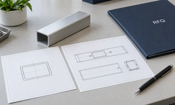
- A dimensioned profile section and a 3D model where available.
- Finished-part drawings for each cut length and fabrication variant.
- The required alloy, temper and material documentation.
- The dimensions and shape controls that govern assembly.
- The hole, pocket, thread and deburring requirements.
- Finish, masking, visible-surface and appearance-approval requirements.
- The initial quantity, expected repeat orders and requested delivery dates.
- Sample, inspection, tooling and revision-control requirements.
Use the same units across the file package and identify how each finished item relates to the common section. Make the dimensions for the extrusion stage and the finished-part stage easy to find.
Ask the supplier to list unresolved questions before tooling is released. A quotation should identify the proposed manufacturing scope and the requirements that still need approval.
Frequently asked questions
1. Can every feature of a finished part be made by the extrusion die?
Plan the continuous section and local features separately. Conventional extrusion creates the repeated section along the length. Local windows, transverse holes and specified threads may need later operations. Show them on the finished-part drawing and ask the supplier to confirm the complete route before approving tooling.
2. What is the minimum wall thickness for a custom aluminum extrusion?
Have the extruder review the actual section and material. The feasible wall thickness depends on the surrounding geometry and tooling and equipment. Identify the thinnest walls and explain their function. Agree a manufacturable design and its acceptance criteria before releasing the die.
3. Is a hollow profile automatically harder to make than an open profile?
Ask for a review of the actual shape. A closed cavity, a narrow opening or a deep channel can introduce different die-design questions. Provide the section dimensions and functional constraints so the extruder can assess the proposed profile and suggest changes where useful.
4. Can secondary CNC machining provide the final precision features?
It can be considered where the geometry, stock and locating scheme support the operation. Identify the final dimensions, datums and accessible machining surfaces. Have the supplier review the extrusion and finished-part drawings together, then confirm the achievable result and inspection method for those features.
5. Should extrusion dimensions be checked before or after finishing?
Define the acceptance stage for each requirement. Section checks can form part of extrusion approval; finished interfaces need checks in their specified final condition. Identify surfaces affected by machining or coating and agree the measurement sequence, masking and assembly test before ordering.
6. How should I approve a profile used with a sliding cover?
Check the mating geometry and test a representative finished length with the approved cover and finish. Include any straightness or twist requirements that affect the engagement. Record whether samples were adjusted during fitting, and define how production parts will meet the accepted fit.
7. What should I send Zenbot before requesting a custom extrusion die?
Send the profile section, finished-part drawings, material condition and quantities. Include critical fits, secondary operations, finish and sample-approval requirements. Mention expected repeat orders and possible length variants. Zenbot can review the proposed scope before confirming the manufacturing route, tooling, price and lead time.
Request a review of your aluminum profile
Send the section and finished-part requirements through Zenbot’s RFQ form. Mark the interfaces that control fit and identify the decisions still open. The review can then address the extrusion die and the operations needed to supply the finished component.